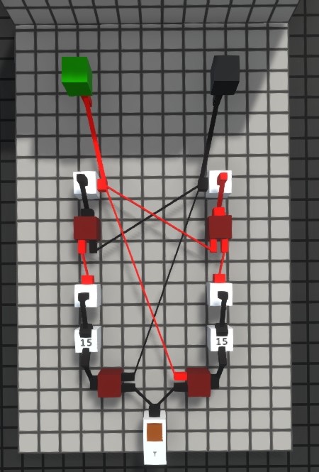
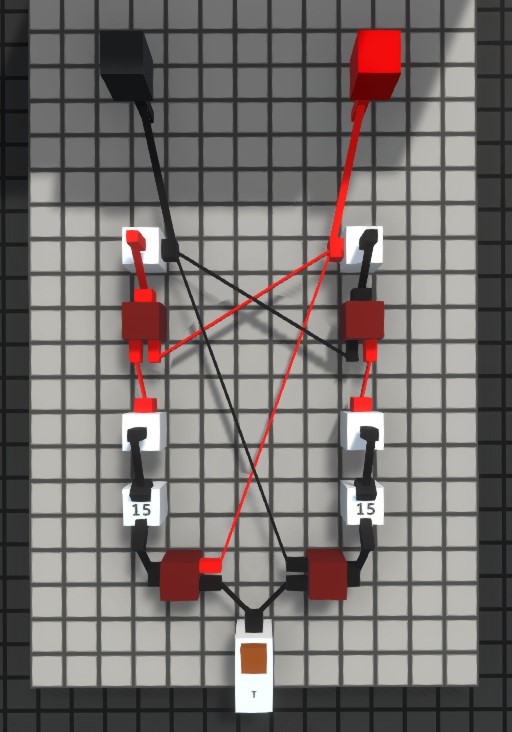
For Logic World players, this is a guide about simple Flip-Flops and Latches, I wll explain them with picture below, let’s check them out.
General
“In electronics, a flip-flop or latch is a circuit that has two stable states and can be used to store state information.” Flip-flops are made of smaller components called logic gates. This guide shows how they work and how to make them in Logic World
SR latch
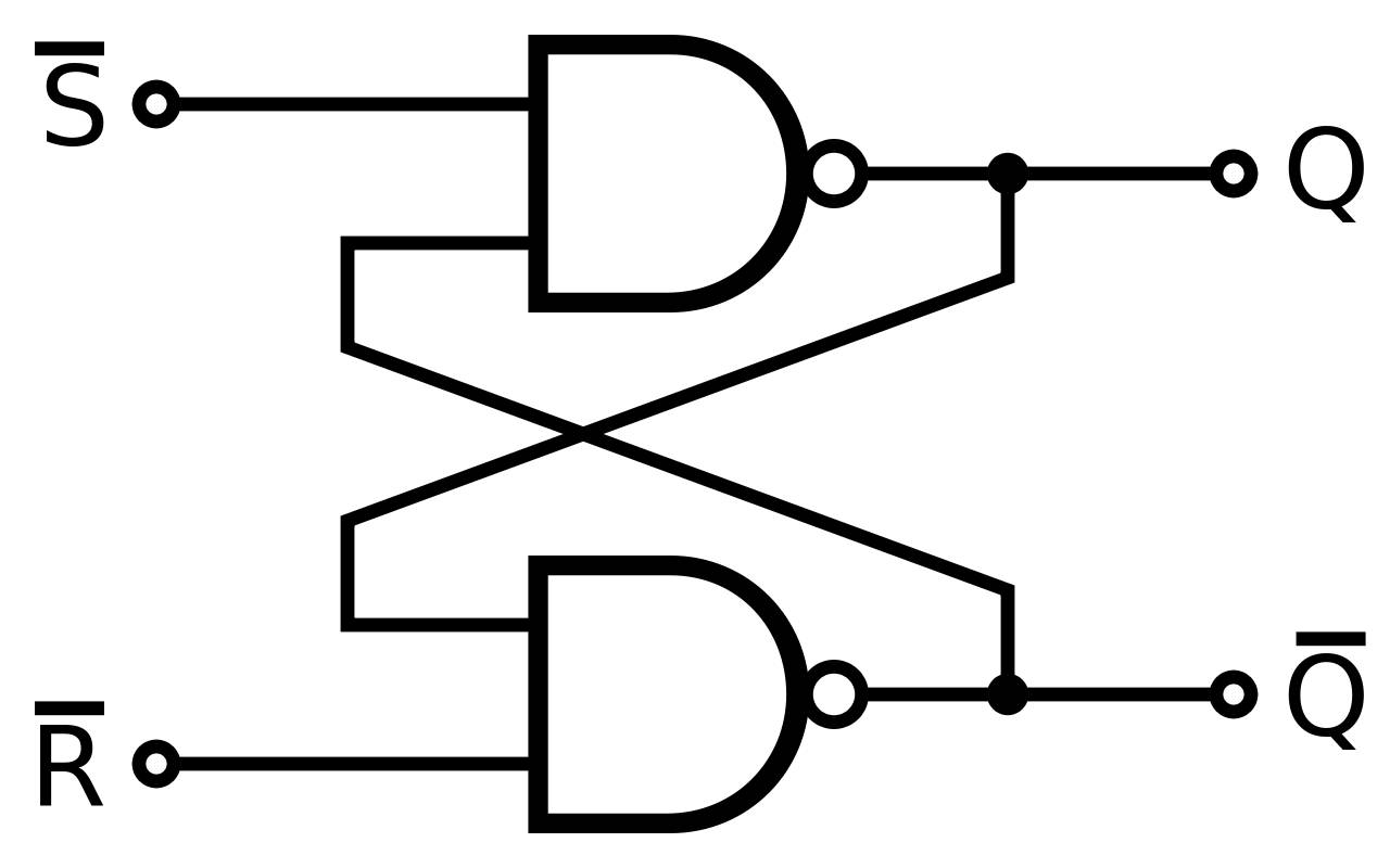
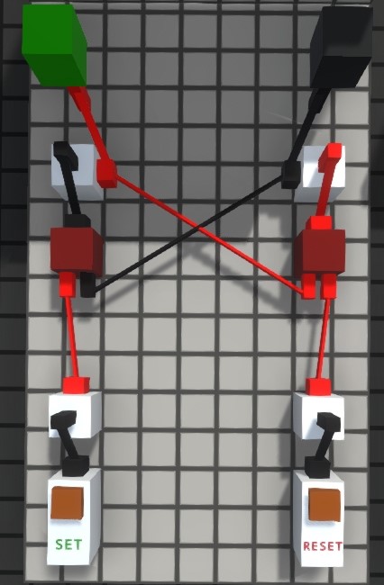
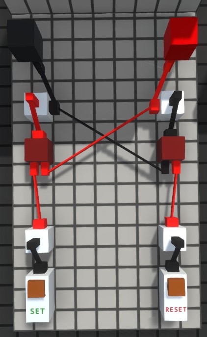
SR or Set-Reset latches are used to set the output to 1 with S input and reset to 0 with R input.
SR latches take two inputs and give one output based on input combination as following:
SR latches take two inputs and give one output based on input combination as following:
S
R
Q
0
0
Q
1
0
1
0
1
0
1
1
X*
*X – forbidden state
Diagram:
In-game:
JK latch
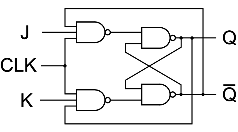
JK latches are similar in behaviour as SR latches, but instead of having the forbidden state, they have the “flip” state, which means the next output is going to be inversed current output.
JK latches also take two inputs and give one output based on input combination as following:
JK latches also take two inputs and give one output based on input combination as following:
J
K
Q
0
0
Q
1
0
1
0
1
0
1
1
Q’
Diagram:
In-game:
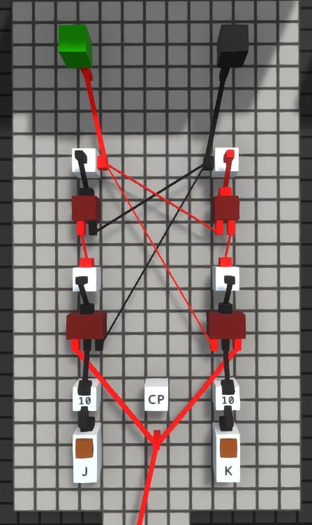
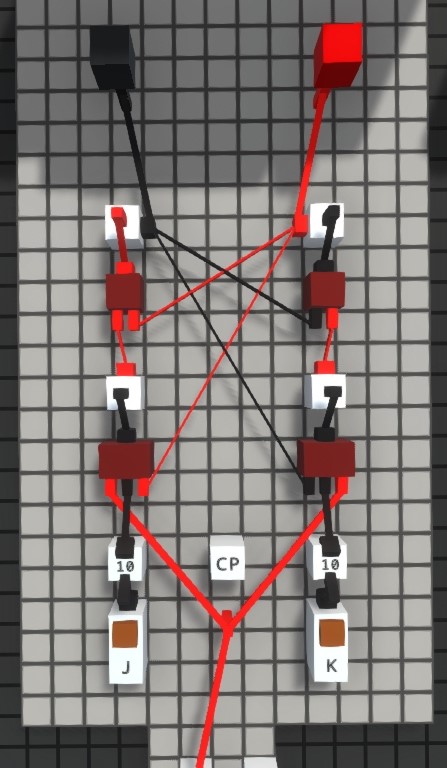
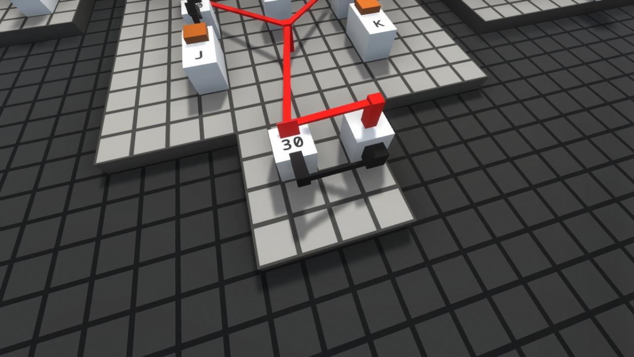
As seen, JK latch has an additional signal CP or CLK (Clock) which controls how often inputs affect the latch. Easiest way to make a clock is to connect output of a delayer to input of inverter and vice versa. Any node can be used as an output. Notice that frequency can be changed by editing the delayer.
T Latch
T latches have one input connected to both inputs of an JK latch so it only has the “flip” state.
T latches take one input and give one output based on input combination as following:
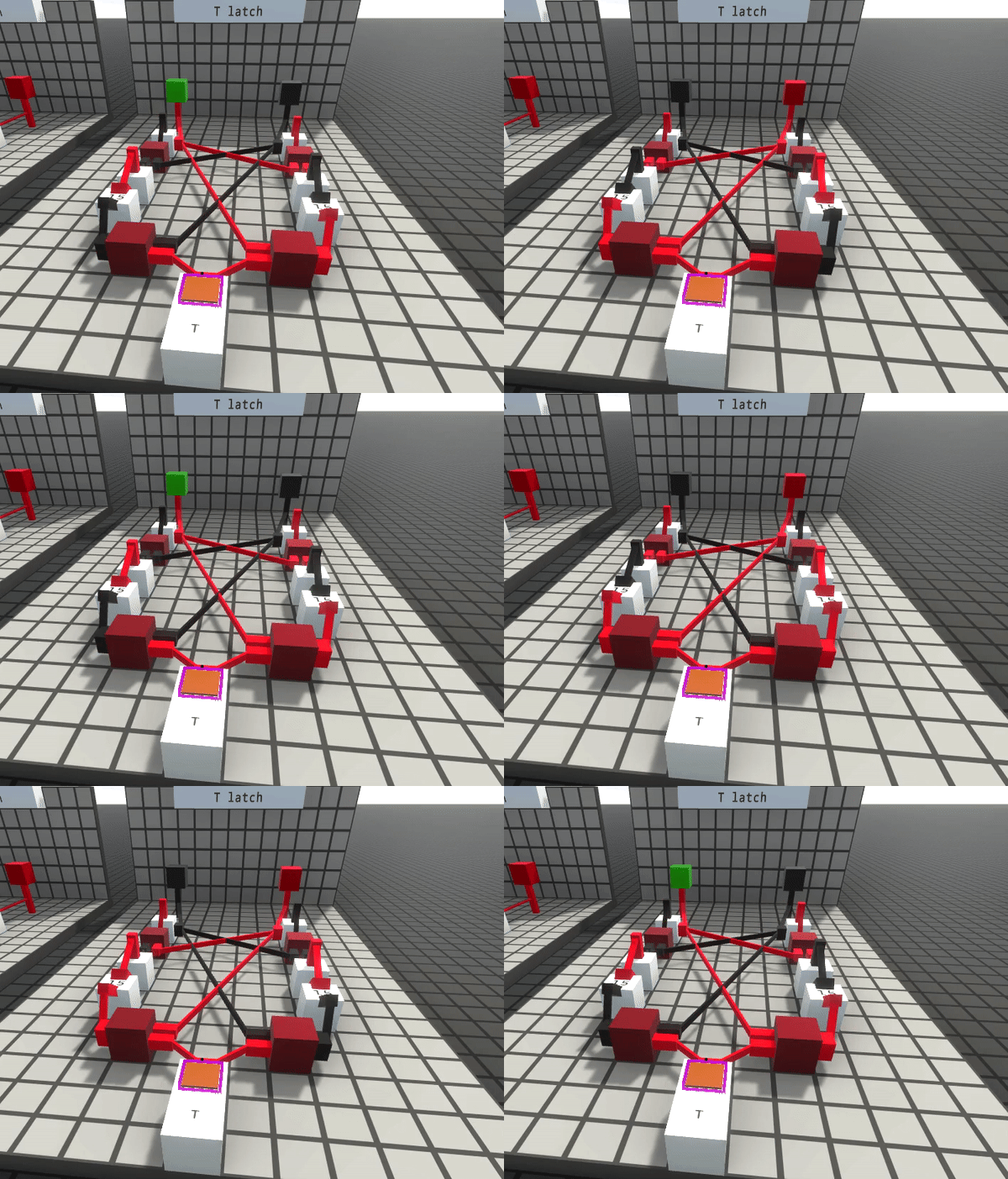
T latches take one input and give one output based on input combination as following:
T
Q
0
Q
1
Q’
Diagram:
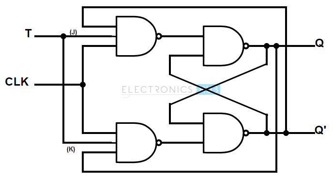
Notice the diagram has a clock, but I haven’t used it because I added the delayers inside the circuit.
In-game:
