For Logic World players, this guide is going to provides you a list of building block, and they are all explained with details, let’s check them out.
Introduction
What will it say?
For now, the description of the elements that are already in the game.
Later the remaining logic modules and flip-flops, maybe also timers / clock generators and counters.
A KV table (status table) for each module.
Will there be an english translation?
Well, it is possible, but not in the beginning.
Inverter (NOT)
As the name suggests, it inverts the signal.

Diode (buffer)
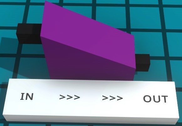
relay
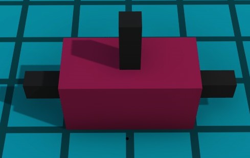 The signal flow can be controlled with the contact on the relay.
The signal can pass through the relay in both directions.
AND


There would only be a signal at the output when both inputs have a 1, but the signal at the output would only drop out again when both inputs are 0.
OR (OR)
Simple variant with diodes (buffers):
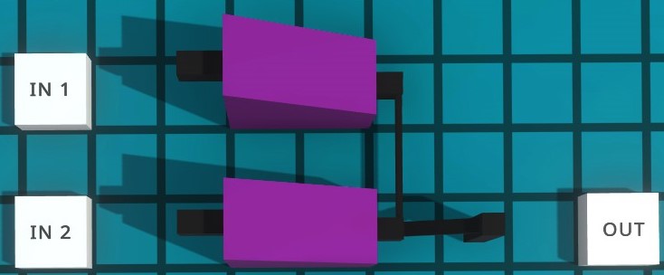 Connect the outputs of the diodes (buffers) and the OR is done.
OR off AND:
 Connect an AND with inverters (NOT) and you get an OR.
NAND
 With an AND and NOT one can easily be built.
An alternative can also be built from an OR:

NOR
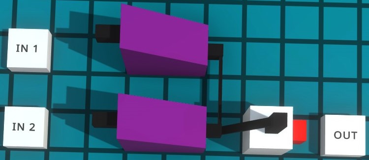 But you only need to switch an inversion after an OR.
Alternatively, you can also build from one AND one:
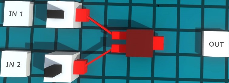
XOR
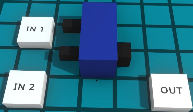 Unlike the AND, this cannot be expanded.
XNOR
 But you only need to extend an XOR with an invert.
D flip-flop (D latch)
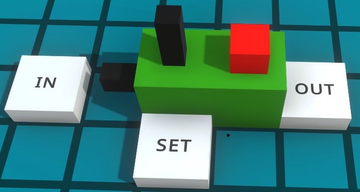 As long as there is a signal at the SET input, it is possible to change the output signal.
As soon as the signal at SET changes to 0, the last signal at IN is saved for the output.
Or you can build it yourself:

RS flip flop
But you can build one from the prefabricated D flip-flop:
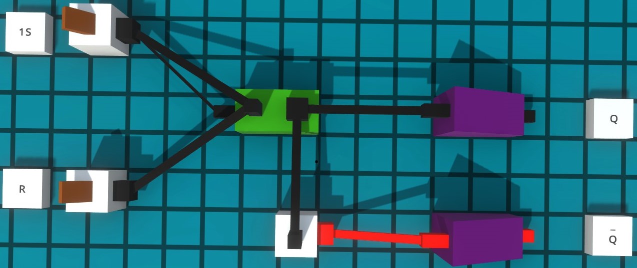 The S input has priority due to the construction of the element, i.e. if there is a 1 at S and R, output Q is set.
An extension gives priority to reset:
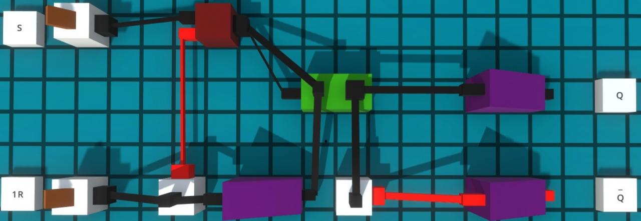 The R input has priority due to the design of the element, i.e. if S and R are 1, output Q is reset .
A self-made from NOR elements:
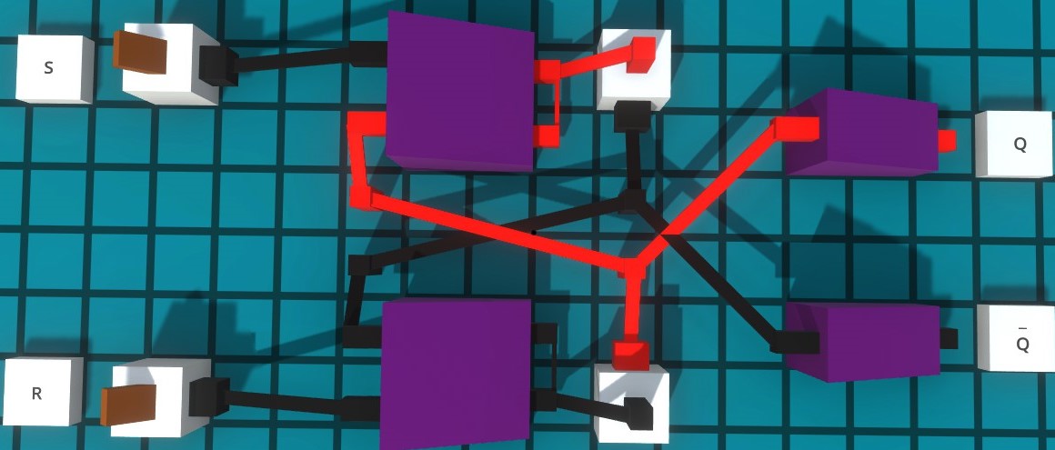 With a simultaneous signal at R and S, both outputs output a 0.
The link can begin to oscillate after the signals at S and R go back to 0. It is recommended to use RS Glider with priority on one input.
With priority on S:
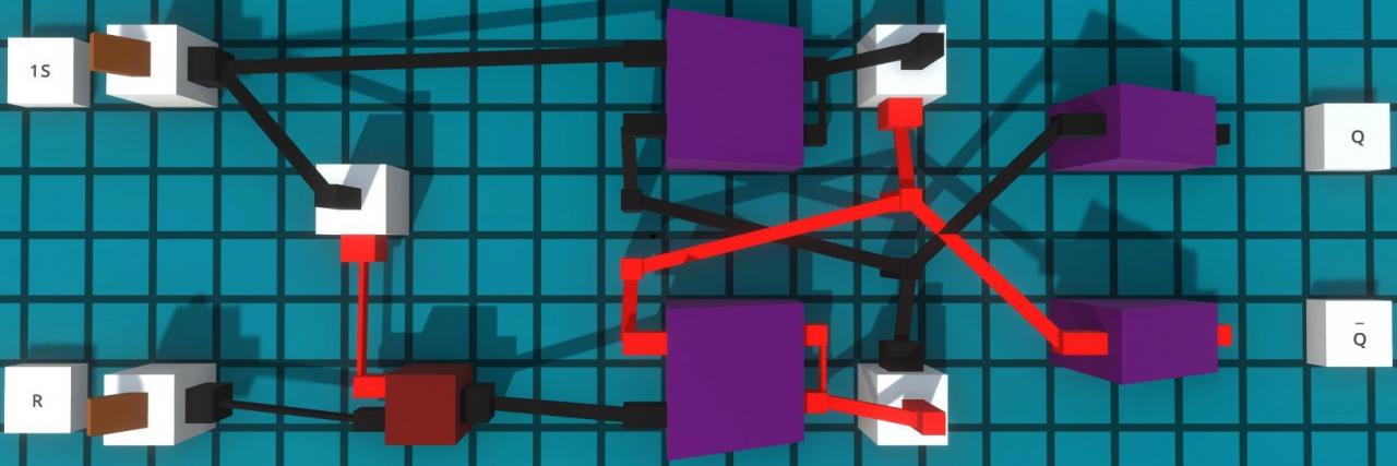 In order to prevent the indefinite switching state, a priority is to be set here.
A self-made one from NAND elements:
 With a simultaneous signal at R and S, both outputs output a 1.
The link can begin to oscillate after the signals at S and R go back to 0. It is recommended to use RS Glider with priority on one input.
With priority on S:
 In order to prevent the indefinite switching state, a priority is to be set here.
RS flip flop with clock / switching input
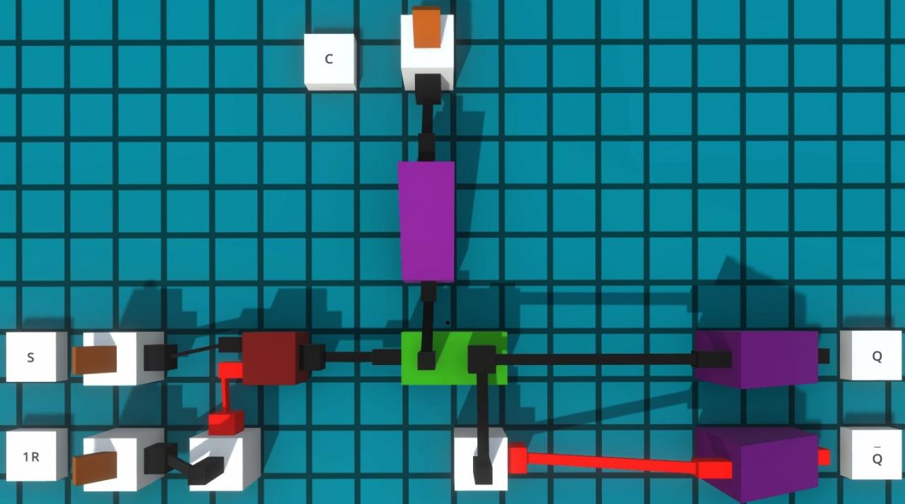 The R input has a priority here.
The signal is set as long as C has a 1; if it is 0, the status is saved.
It is also possible to build one yourself from NANDs: However,
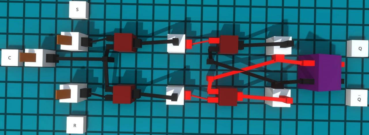 this example has no priority input and, like the normal RS-NAND, is unstable with the same signal on the S and R.
Delayer
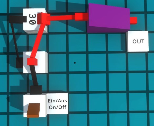
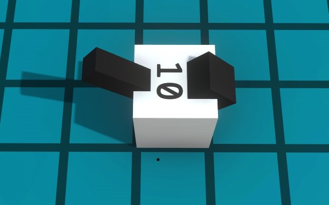 It is adjustable from 1 to 30 and delays the arrival and departure of the signal.
One cannot separate this.
Unfortunately I cannot say what the time base for the setting is.
10 works like 1 sec, but 30 only works like 2.5 sec.
Oracle
 If there is a signal at the input, a signal or no signal is randomly output at the output.
If there is no signal at the input, there is always no signal at the output.
Simple clock
