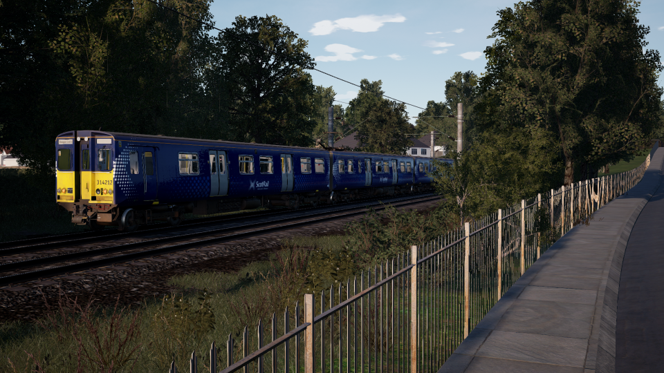
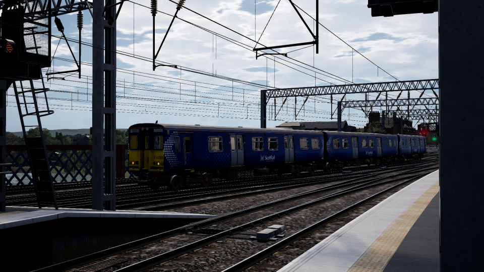
For Train Sim World 2 players, this guide is an introduction to the newly released Cathcart Circle DLC, including the BR Class 314, Signalling and safety syste, let’s check it out.
Introduction
A PDF version of this guide can be downloaded here: https://forums.dovetailgames.com/threads/cathcart-circle-quick-guide.41502/
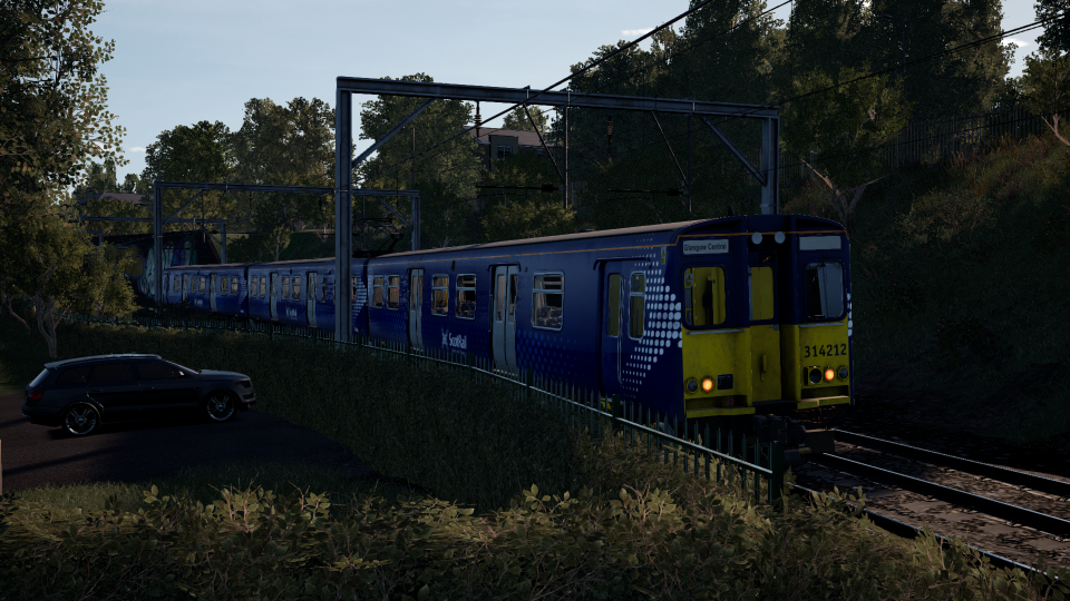
The BR Class 314
The Class 314 units were withdrawn in 2019 as they were not compliant with People of Reduced Mobility (PRM) regulations which came into force on 1st January 2020. 15 units were scrapped, with one (314209) held back for trial conversion to hydrogen power, as part of a feasibility study running alongside ScotRail’s commitment to withdraw all diesel traction by 2035.
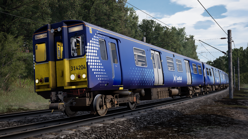
The Class 314 in Train Sim World 2 comes in ScotRail Saltire livery, introduced since 2008 and would eventually be applied to all trains operated by the holder of the ScotRail franchise, including those operated on behalf of Strathclyde Partnership for Transport (SPT), which, at the time, had its units in a carmine and cream livery. Though most of the Class 314 fleet still wore this livery when they were withdrawn in 2019, it was not included in the pack.
Cab Diagrams
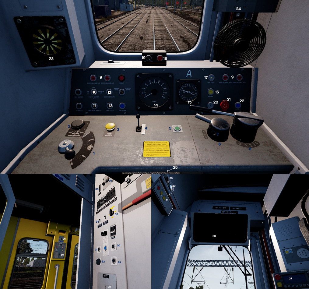
Explanation:
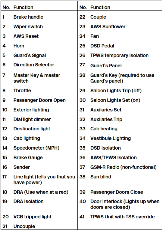
Cab Set-Up and Changing Ends
- Set the brake handle to full service.
- Insert the master key, setting the master switch to on.
- Check the line light is on.
- On the back wall, enable AWS, TPWS and DSD, if you wish.
- Set the exterior lights to Head/Marker Lts
- If necessary, set the Instrument Dimmer to High, and the Destination Light to on.
- Set the directional selector to neutral.
- Open the doors if necessary.
- Set the directional selector to forward.
- Close the doors, release the brakes, and you’re good to go.
In order to shut down the cab;
- Set the brake to full service.
- Set the exterior lights to Tail Lts.
- Set the directional selector to off.
- Set the instrument dimmer to low.
- Set the master switch to off, and remove the master key.
Brakes
new EMUs and DMUs in the 1970s and 1980s. This means you have 3 set
steps of braking, plus release and emergency. You can see what the
brakes are doing using the small gauge to the right of the speedometer.
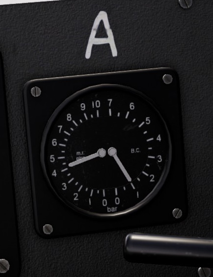
The needle on the left indicates the main reservoir pressure (MR). This must read above 6 bar for the brakes to work properly. If it drops to below 6 bar, the compressor will automatically kick in to bring it
back up. The right needle is the brake cylinder pressure (BC). This tells you how hard the brakes are applied.
If the BC reads 0, the brakes are released. The higher it reads, the harder
the brakes are applied. Note that the Class 314 uses blended rheostatic
braking, so the motors are run in the opposite direction to slow the train
down, with a little bit of normal braking. As such, the BC will be low
(typically below 1 bar) until the train is close to stopping.
To perform a brake check on the unit, while stationary and with the
passenger doors closed:
- Set the brake to step 1. Check the BC reads approximately 1 bar.
- Set the brake to step 2. Check the BC reads approx. 2 bar.
- Set the brake to full service. Check the BC reads between 3 and 3.5 bar.
- Set the brake to emergency. Check the BC reads between 4 and 4.5 bar.
- Release the brakes. Check the BC reads 0, then immediately re-apply the brakes.
For a full guide to braking in TSW, please watch this:
The Route
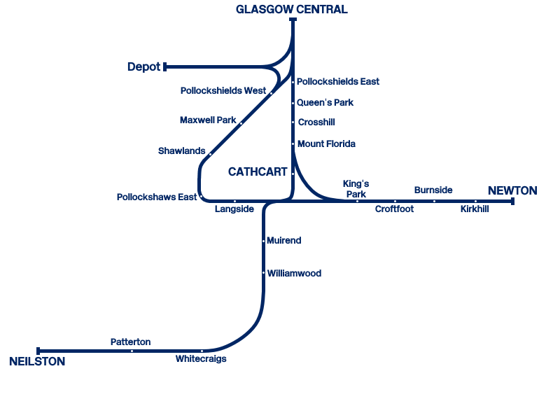
The services operated are:
– Glasgow – Glasgow via Cathcart (both clockwise and anti-clockwise)
– Glasgow – Neilston via Cathcart
– Glasgow – Newton via Mount Florida
– Glasgow – Newton via Shawlands
All services stop at all stations, although there are some non-stop empty stock movements, as well as depot movements.
Additional services can be gained through the following:
– One additional freight service between Newton and Glasgow is enabled for owners of the East Coastway DLC.
– A railtour service (split into two halves) between Glasgow and Newton via Neilston is enabled for owners of the Northern Trans-Pennine DLC.
The route comes with 6 scenarios and 2 tutorials.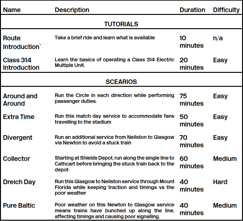
` The route introduction automatically plays when the route is loaded for the first time.
Signalling
NB: This guide will talk about the systems employed in the Cathcart Circle DLC only; it is not generalised to the whole system. For a fuller picture of signalling in the UK, please watch this video:
Signals in the UK can display up to 4 aspects (colours), these are:
- Red/Danger, which tells the driver to stop the train before the signal.
- Single Yellow/Caution, which tells the driver the next signal is at danger, so prepare to stop.
- Double Yellow/Preliminary Caution, which tells the driver the next signal is at caution, so prepare to slow the train down.
- Green/Clear, which means the line ahead is clear and no further action needs to be taken.
- A signal that is not displaying any aspect should be taken as a red/danger signal – obtain instructions from the signaller.
Some signals are incapable of displaying a double yellow. These are generally deployed where the speed limit and route type is such that preliminary caution is not necessary. 4 aspect signals, however, can be deployed in areas of low speed limits, such as on the approach to a terminus.
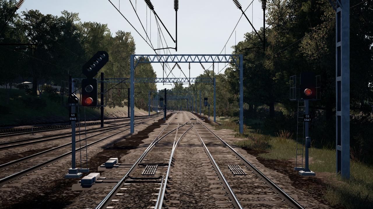 Above are 2 examples of the newer LED signals. The signal on the left is a 4-aspect signal (it is capable of displaying extra information – we’ll get to that in a bit though), and the one on the right is a 3-aspect. LED signals use the same light to display each aspect, unlike bulb signals, which look more like a standard road traffic light. 3-aspect signals cannot display preliminary caution.
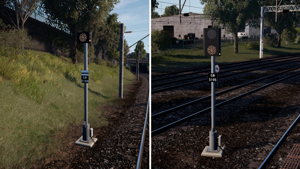
To indicate a route a train is set to take, signals can be fitted with angled lights (feathered signals) or a digital display (theatre signals).
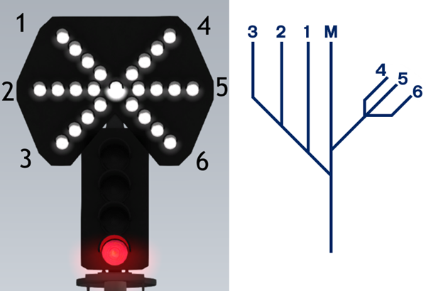
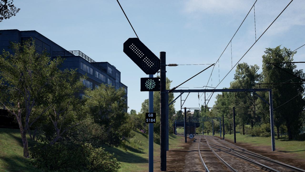 A feathered signal looks like this and uses a series of lights to indicate the route. 7 paths can be shown using these. The diagram below illustrates what each feather means.
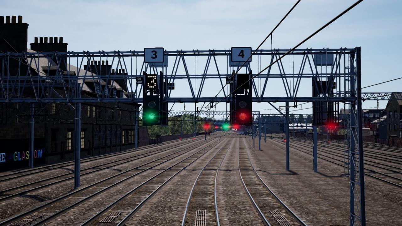 Theatre signals use digital screens to display alpha-numeric codes to indicate to the driver which path the train will take. As there are a theoretically infinite number of possible paths, it’s impossible to list them all, but here are some common ones:
– S: Siding
– B: Branch
– C: Cathcart (this route only)
– UM: Up Main
– DM: Down Main
– A number will typically indicate a platform, or, in the case of the above, a numbered track.
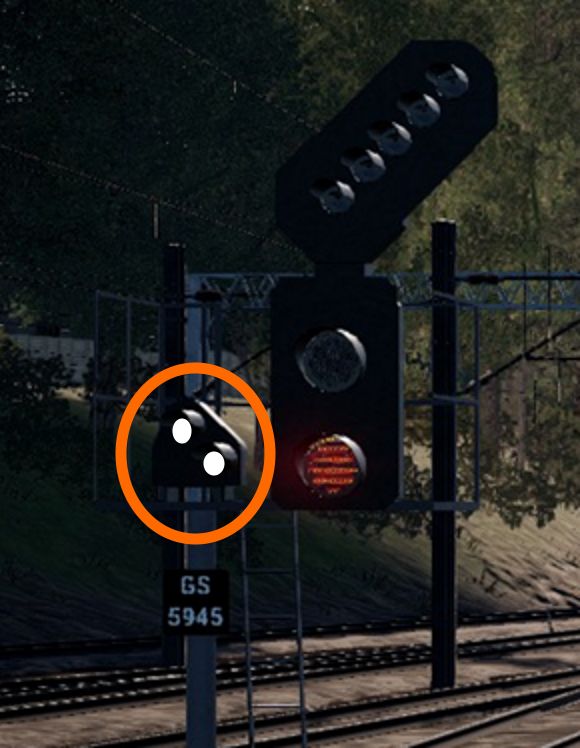
Sometimes it is necessary to pass a signal at danger, for example, to enter a platform already occupied by a train in order to couple to it. Where this is common, a ‘call on’ is provided, which will illuminate two white lights at 45 degrees, as seen on the left, once permission has been obtained from the signaller.
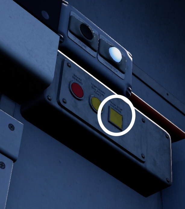
If a call on is not provided and a signal must be passed at danger (such as in the ‘Collector’ scenario), the signaller will provide instructions to the driver. In this case, the train’s TPWS Train Stop Override must be used if TPWS is enabled. This will prevent a brake demand penalty brake application.
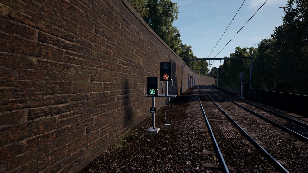 At Pollockshields, there is this rather odd-looking signal. This is a split distant signal. They are rare on the network and act as a distant signal for an upcoming junction signal, providing advanced warning of the aspect of the upcoming signal. The left signal applies to trains taking the left hand line with the right signal for trains taking the right hand line.
Safety Systems
AWS (Automatic Warning System) was developed in the 1960s as a means of relaying the signal aspect to the driver – it is itself based on an earlier system known as ATC developed by the Great Western Railway in the very early 20th century in response to the 1900 Slough Rail Accident, where both the driver and fireman failed to see 2 danger signals which would’ve prevented the express train they were in charge of hitting another train that had stopped in the station. The main difference between ATC and AWS is that ATC relied on physical contact, whereas AWS relies on magnets (pictured below) placed approximately 200m from the signal, but can be closer if necessary.
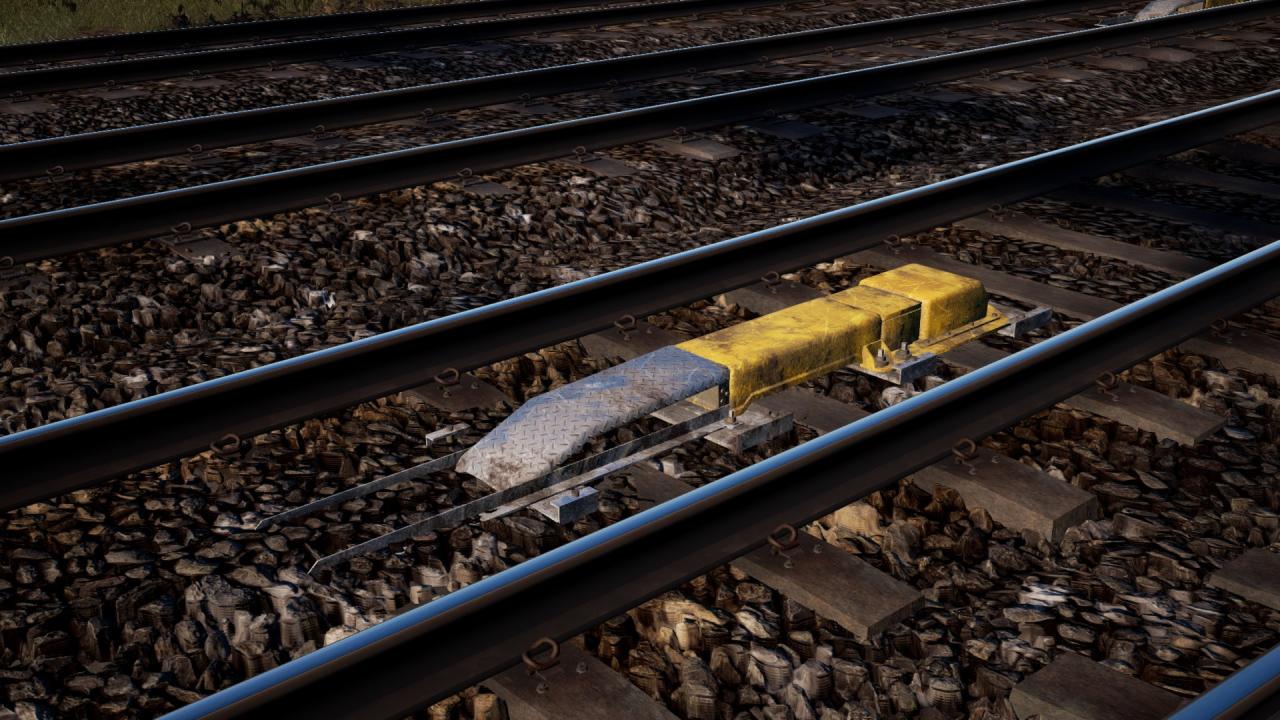
If, and only if, the signal ahead is displaying a clear aspect, a bell will sound in the cab, otherwise a monotone warning horn will sound. This must be acknowledged within 3 seconds, otherwise you’ll be given a penalty brake application.
After the train has stopped, you will need to wait a few minutes until the brakes can be released again, when the TPWS brake demand light goes out. Some magnets are permanently armed so will always give a warning tone. These are typically placed in front of speed restriction warning boards, also known as Morpeth boards, if the drop in speed limit is great enough.
The Train Protection & Warning System (TPWS) was developed in the late 1990s after it became apparent that fitting the entire network with Automatic Train Protection (ATP), as seen on the Great Western Main Line and Chiltern Main Line, was not practical.
Unlike ATP, which is meant to prevent trains passing signals at danger all together, TPWS’s primary function is to mitigate the consequences of trains passing red lights, though is not to be confused with the earlier Moorgate Protection (employed on the London Underground) and Indusi (German system employed on the Tyne & Wear Metro) systems, which use electro-mechanical technology. TPWS uses a transmitter mounted to the tack.
Two types of TPWS are employed. The Train Stop Sensor (TSS) grid (below) is fitted to the track, next to signals, and if the signal is at danger will induce an emergency brake application if a train passes over it (provided the train is also fitted with TPWS).
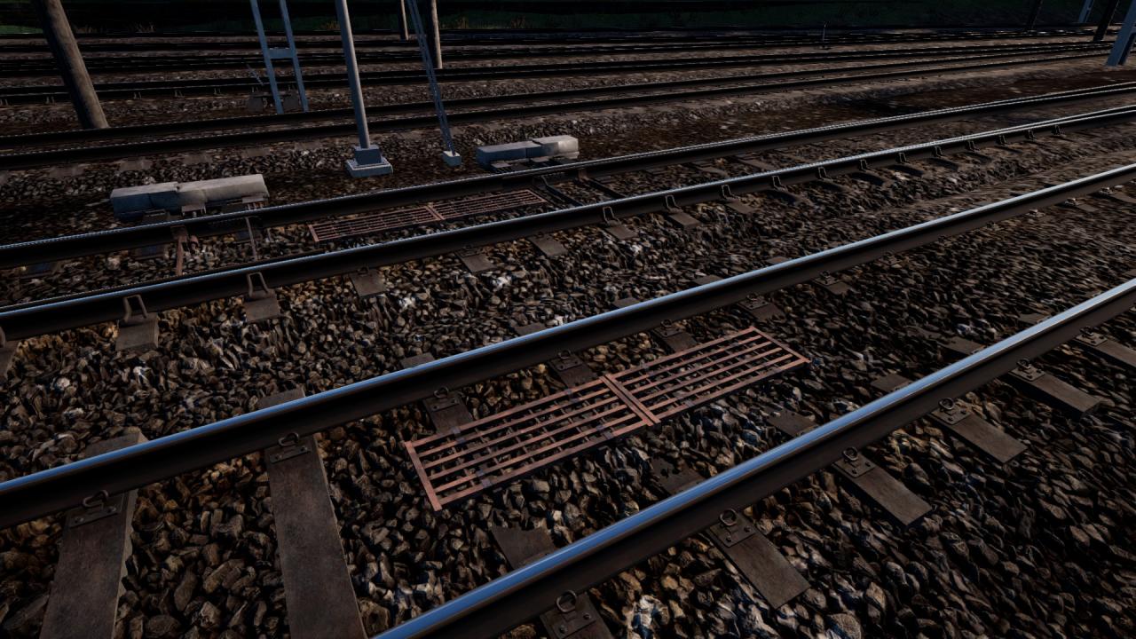
The second type is the Overspeed Sensor (OSS), which is fitted in particularly high-risk areas, such as on a high speed main line, or where many trains are likely to be running in a short space. These are placed in advance of the signal, and in advance of some buffer stops, to stop a train if it is going too fast. This system uses two smaller grids placed apart from each other.
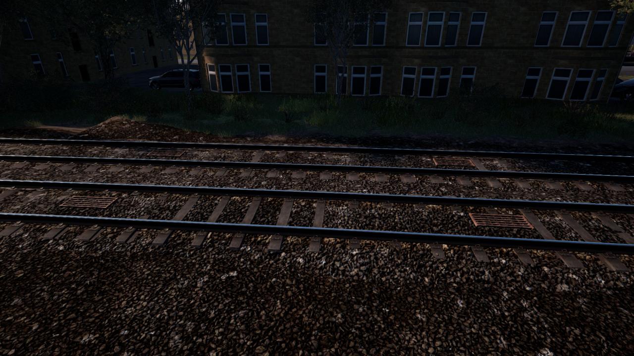 TPWS OSS is not currently functional in Train Sim World 2.
A Driver’s Safety Device (DSD), also known as the dead man’s pedal/handle is provided. This is a very simple system. The driver must apply pressure with their foot on the pedal at all times while the train is moving, else the train brakes will apply (they will release as soon as pressure is re-applied).
The Class 314 is not fitted with a Driver Vigilance Device (DVD), where an alarm (which must be acknowledged) sounds every 30-60 seconds.
The Driver’s Reminder Appliance (DRA) is provided in the cab. It is designed to be used at stations where the starting signal is at danger, or non-existant. The DRA will prevent power being applied when activated, to remind the driver of a potential danger signal ahead. Another method drivers use is to put the train in neutral in conjunction with the DRA in such situations.
Remember, after doing platform duties – Signal, Platform, Signal, Action.
– Signal: Check the signal aspect.
– Platform: Check the platform to ensure it’s safe to depart.
– Signal: Check the signal again.
– Action: Move the train if the signal allows.
This training video from the early 2000s contains a good example (the first one) as to when and why you should set the DRA:
