

The jump from tutorial platform to functional spacecraft is where most new pilots lose their ships — and their patience. You have the components, the grid, and a vague idea of what a spaceship should look like, but the wiring, thruster orientation, and control bindings can turn a promising build into a lawn dart in seconds. This guide gives you a complete, tested path from an empty platform to a successful first flight, covering frame construction, RCS and main thruster setup, control wiring, and the auxiliary systems that make a ship actually usable. No theory, just the exact steps and numbers you need.
Clearing the Platform and Reading Your Objectives
Start by pressing Control+G to select every component on the platform, then press X to delete them all. This gives you the same blank slate you had right after the tutorial ended.
Press O to open your objectives. The first mission, “Lost in Transit”, requires you to pick up a package measuring 1.2 x 1.2 x 1.2 — small enough to fit through a narrow gate. That dimension sets your minimum ship size; build around it or you will not clear the gate.
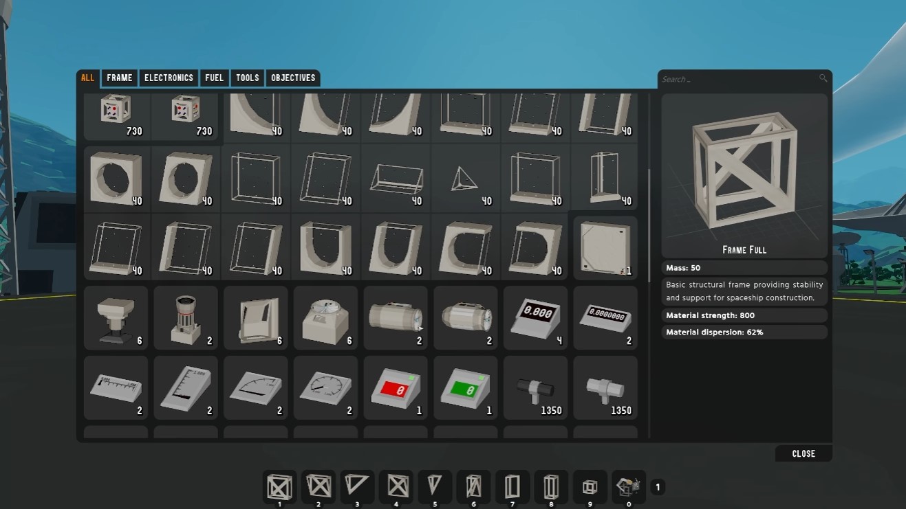
Open your inventory and check component counts. The numbers (e.g., 730 frames, 40 windows) are per category, not per individual block type. Drag frequently used parts to your toolbar for quick access, and use Control+1 through Control+0 to switch between toolbar pages.
Frame Construction: Placement, Copying, and Structural Integrity
Drop your first frame block anywhere on the platform. All blocks share the same grid, so they will connect regardless of where you start.
Use Spacebar to jump and double-tap Shift to enable the jetpack for easier vertical building. To copy a section of your build:
- Press G to enter selection mode.
- Right-click to set a corner, drag to define the area, then right-click again to finish.
- Press C to duplicate the selection.
- Move it into position and press E to confirm placement.
- Use the mouse wheel to move the selection vertically.
The welder tool welds armor panels and increases structural integrity and shear strength of mounted components, but it also adds weight. Press H to open debug mode, which displays weight and center of mass. Weld symmetrically to keep the center of mass centered — an off-center build will fight you in flight.
Leave the front of the ship open for now so you can run wires easily. Place the seat and use its lever to adjust height. Keep controllers set back from the front edge to leave room for cable routing.
RCS Thrusters: Wiring, Placement, and Configuration
Press M to open the manual for setup guidance. For RCS, you need:
- A Joystick 3D
- An RCS controller
- A battery
- Data cables and power cables
Place the joystick and label it by pressing E on its front label. On the RCS controller, the ports are color-coded: red is power, yellow is data input, blue is data output. Connect the joystick’s data output to the controller’s data input, then run power from a battery to the controller.
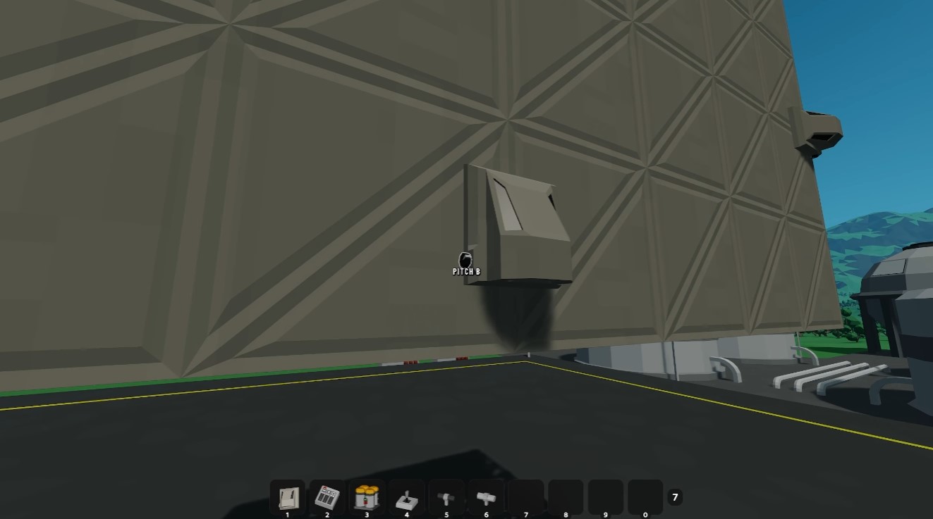
Place RCS thrusters according to the manual. Each thruster has a knob that cycles through configurations. The correct placement is:
| Configuration | Position |
|---|---|
| Roll B | Left |
| Roll A | Right |
| Yaw A | Right |
| Yaw B | Left |
| Pitch A | Bottom |
| Pitch B | Top |
Protect exposed thrusters with dampeners. Weld armor plates at the bottom corners and place dampeners on them. The gray side of a dampener is the top; the black side is the bottom.
Hold R to enter sim mode and test your setup. Hold R again to return to build mode.
Main Thrusters: Power Circuits and Data Routing
For atmospheric flight, you have three options:
- Atmospheric thrusters — one-directional
- Atmospheric fans — bi-directional
- Atmospheric lift fans — vertical thrust
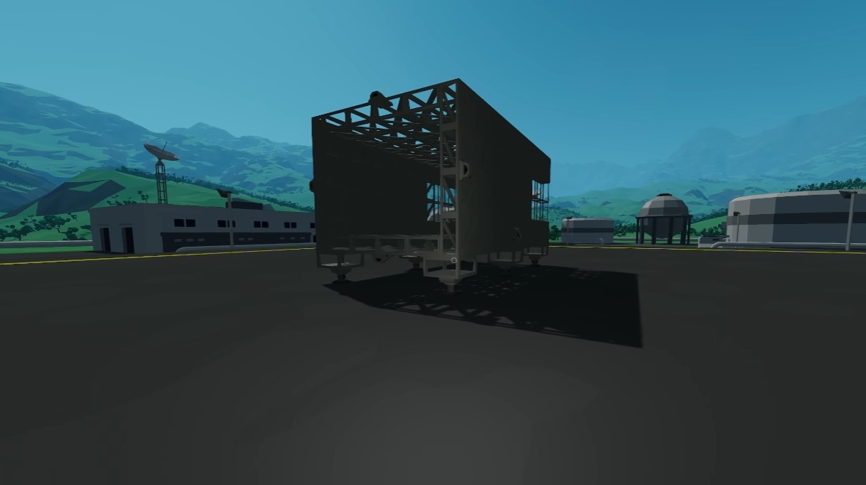
Place bi-directional fans for forward/backward thrust, aligned with the center of mass (check with H). Place lift fans symmetrically around the vertical center of gravity.
Power consumption matters:
| Component | Power Draw |
|---|---|
| Bi-directional fan | 8 power/sec |
| Lift fan | 4 power/sec |
Batteries are non-rechargeable, but they reset to full charge when you enter ship mode. Use a power router to connect all batteries and thrusters on a single circuit — power has no direction, so routing is forgiving. Use frame quarter with ports blocks to run power and data through walls.
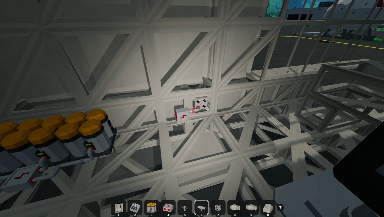
To delete a wrong cable, press Control+Alt to select the entire run, then right-click to delete it. Use a data router to combine data circuits; remember the color rule: yellow (input) to blue (output).
Levers, Key Bindings, and First Flight Testing
Place two vertical levers: one for forward/reverse and one for vertical thrust. The data port is on the back; the label is on the front. For forward/reverse, press the button on the right side of the lever to switch from 0-100 to bidirectional (-100 to 100).
Wire the vertical thrust data to one data router and the forward/reverse to a separate router. Inside the ship, connect these routers to the corresponding levers.
In the seat, press Left Alt to edit key bindings. Assign keys like:
- W/S for forward/reverse
- Space/C for vertical
- E/Q for roll
Note that key bindings override default actions — binding E to roll means E will no longer exit the seat.
Set levers to desired default positions before entering ship mode. A lever set to 74 will cause the ship to take off immediately, so double-check your defaults. Use Control while adjusting levers for precision mode.
If the ship spins, flip the polarity switch on one of the forward/reverse thrusters. If pitch is inverted, swap pitch A and pitch B on the RCS thrusters. Offset thrust from the center of mass will cause unwanted rotation — check your debug overlay before blaming the wiring.
Gates, Radar, Gyro-Line, Camera, and Altimeter
Add a gate to secure packages. It has power and data ports. Control it with a switch or a lever — a lever allows partial opening. Ensure the gate is set to open in build mode to avoid locking yourself out.
For navigation, add a radar. It needs power only, has one sticky side (the back), and a rotation knob. In ship mode, the radar shows a zoom level, a crosshair (you are the center), and objectives as squares.
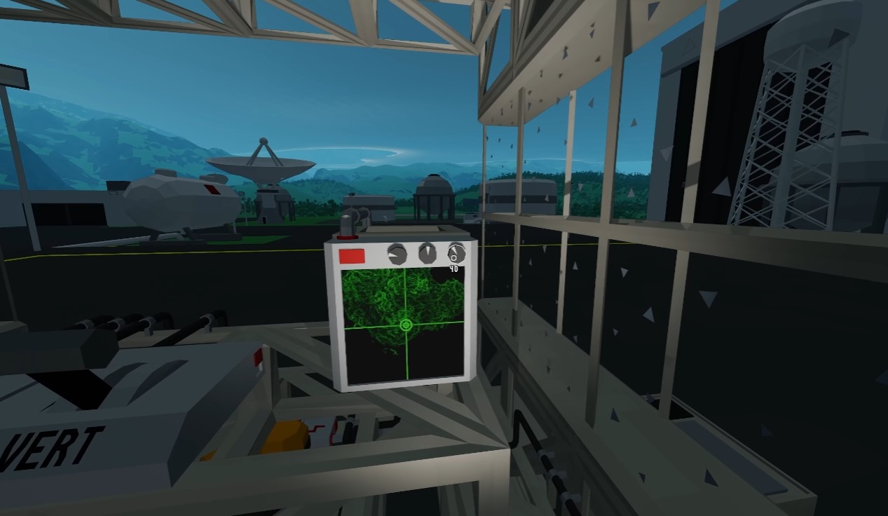
The gyro-line shows pitch and roll orientation. It needs power and can output data. Add a camera and CRT monitor for landing views; both need power, and the camera sends data to the monitor. Adjust the camera’s rotation knob to align the view.
Add an altimeter and a data meter. The altimeter measures height above sea level and must be mounted outside with an unobstructed view. The data meter has an input and output for data.
Windows, Blueprints, and Moon Landing Prep
When closing the front of the ship, use windows with armor on the bottom. Windows without armor will fall out.
Press B to open blueprints. Press the plus button to save a blueprint, and use Load to load a saved ship. Save often — rebuilding a ship from scratch is painful.
After completing the second mission, you unlock electric thrusters for space travel. You only get two, so mount them as vertical thrusters on your center of vertical mass for moon landings. Use RCS thrust for forward movement by tilting.
Note: If components aren’t working, check all connections first. It is almost always a wiring issue. Components are on by default once powered.